Jun 10 • Jordan Felber

How to Integrate Google Earth with AutoCAD for Landscape Design

computer keyboard with keys
When beginning a landscape design project, one of the most crucial steps is understanding the site’s context. Satellite imagery is an excellent resource for getting a comprehensive overview of a property and its surrounding features.

In this guide, we'll show you how to export a Google Earth image and import it into AutoCAD as a base layer, providing a strong foundation for your design process.

Why Start with Satellite Imagery?

Satellite images are a quick and accessible way to gather context for a site.

They give you a bird’s-eye view of not only the property itself but also the surrounding environment, such as neighboring properties, roads, and existing vegetation.

This helps landscape designers understand how the site relates to its context, identify opportunities for screening, and plan for visual privacy and functional site design.

Step 1: Export the Image from Google Earth

To get started, open Google Earth Pro—a free satellite imagery desktop tool that offers more advanced features than the browser version. Once open, use the search bar to locate your project address.

Once Google Earth Pro zooms into the address, take a moment to explore the Layers section in the bottom right corner. Typically, enabling the 3D Buildings and Terrain layers gives you a more realistic view, but if 3D data is unavailable for your site, a flat view is still acceptable.

Navigate to the desired location by clicking and dragging the map or using your mouse scroll wheel to zoom in and out. Often, you’ll notice that the view isn’t perfectly top-down. This can make tracing difficult in AutoCAD, so you’ll want to reorient the view.

For PC users, hold the Control key and move your mouse to adjust the view; for Mac users, hold the Command key. The goal is to achieve a true top-down view with the North Arrow pointing up. An easy shortcut is to press the “R” key, which automatically reorients your view.

Make sure to zoom out just enough to include not only the site but also neighboring properties and relevant context. This additional context is helpful for understanding spatial relationships and planning transitions in your design.

Step 2: Save the Image with Key Information

Once your view is set, click the Save Image icon at the top toolbar (it looks like a small map with a red pin). A menu will appear below with Map Options and Resolution settings.

Here’s what to check:

 Scale: Ensure this is visible, as you’ll use it to scale the image accurately in AutoCAD.
 Compass: This shows the direction of North and is essential for site orientation.

Position your view one final time to include the project area and some surrounding context, then click Save Image. Save the image in a dedicated project or client folder. It’s important to note that AutoCAD does not embed image files—it references them. If you move or delete the image later, AutoCAD will lose the link, and you’ll need to re-import it.

Step 3: Bring the Image into AutoCAD

With your satellite image ready, open AutoCAD. If you’re using a custom template or a Pre-Built CAD Library from a course or CAD library, save a copy of it in the project folder using a descriptive name like “LastName Residence_LPlan_Date.dwg.” If you’re starting from scratch, simply create a new drawing.

Before attaching the image, set the drawing units by typing UNITS in the command bar. Adjust to your preferred unit system (inches, feet, meters, etc.).

Next, type the command 
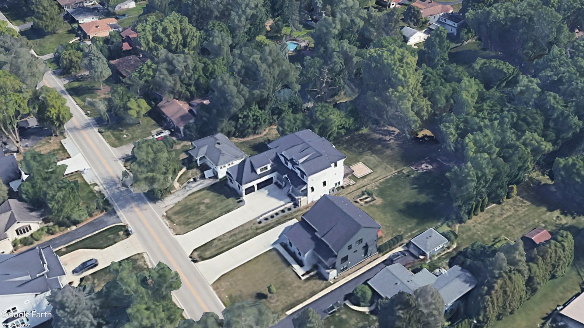
IMAGEATTACH and press Enter. Navigate to where you saved the satellite image, select it, and click Open.

In the dialog box that appears:
 Insertion Point: Check Specify On-Screen.
 Scale: Uncheck Specify On-Screen—we’ll scale it manually.
 Rotation: Leave unchecked, since your image is already oriented with North up.

Click OK and place the image near the drawing origin point for easy reference to import google earth into AutoCAD.

Step 4: Scale the Image Accurately

The next step is to scale the AutoCAD and Google Earth image to match real-world measurements. Use the SCALE command, select the image, and set a base point (usually the left side of the scale bar in the image). Type R for Reference, then click the start and end points of the scale bar in the image.

Enter the known real-world length of that scale (for example, 100 feet or 30 meters) and press Enter. This ensures the entire image is at a 1:1 scale, which is critical for accurate site planning.

It’s essential to verify this scaling with the DIST command. Measure the distance between the same two points you just scaled to confirm it matches the known measurement.

Step 5: Organize Layers and Begin Tracing

To keep your drawing organized, create a new layer for the satellite image. In the Layer Properties Manager, right-click and add a new layer—name it “Google Earth Image.” Select the image, and in the Properties dropdown, assign it to this new layer.

You’re now ready to start tracing site elements, such as buildings and driveways, using Polyline or similar commands. If you’re using a pre-made CAD library, you can select the appropriate layers (like A_BUILDING or L_Existing Concrete) to keep your linework structured. If you’re starting from scratch, create these layers and assign your linework accordingly.

Pro Tip: Enhance Line Visibility

To make tracing easier, adjust the Fade setting of the image. Select the image, find the Fade slider in the Image tab, and reduce the image’s opacity until your linework is clearly visible.

 Learn how to use AutoCAD for Landscape Design here.

Free Downloads & Online Courses