Jul 10 • Jordan Felber

What to Include on a Landscape Architecture Plan

Related — AutoCAD for Landscape Design

sample landscape architecture plan
A landscape architecture plan is much more than a single drawing of patios, planting beds, and walkways. It's a coordinated collection of drawings that communicate how an outdoor environment should be built. Every sheet serves a specific purpose, whether it's documenting existing conditions, identifying materials, locating plants, or explaining construction methods.

For landscape designers, the drawing set becomes the primary communication tool between everyone involved in the project. Clients use it to understand the overall vision. Contractors use it to estimate and construct the work. Builders coordinate it alongside architectural and civil drawings. In many municipalities, permitting departments also review portions of the plan before construction can begin.

When each sheet has a clear objective and contains the appropriate level of information, projects move through design, pricing, approvals, and construction with fewer questions and fewer revisions.

In this guide, we'll walk through the drawings that are commonly included in a professional residential landscape architecture plan, what belongs on each sheet, and why each one contributes to a successful project.

What Is a Landscape Architecture Plan?

A landscape architecture plan is a set of technical drawings that communicates the design intent, layout, materials, planting, and construction information for an outdoor space.

Rather than relying on a single plan view, professional drawing sets separate different types of information across multiple sheets. This allows each drawing to remain clear and readable while giving contractors and consultants the information they need without unnecessary visual clutter.

Depending on the project, a landscape architecture plan may include:
  • Title sheet
  • General notes
  • Existing conditions plan
  • Demolition plan
  • Overall site plan
  • Hardscape plan
  • Planting plan
  • Lighting plan
  • Construction details
  • Elevations and sections
  • Photorealistic renderings


Not every residential project requires every sheet, but organizing information into dedicated drawings creates a workflow that is easier for everyone involved to understand.

Learn How to Use AutoCAD to Design Full Landscapes

Why Landscape Drawing Sets Are Organized Into Separate Sheets

Every construction drawing answers a different set of questions.

A contractor installing pavers doesn't necessarily need to sort through tree symbols and planting schedules while laying out a patio. Likewise, a nursery supplying plant material doesn't need dimensions for retaining walls or footing details.

Separating information into dedicated drawings allows every trade to quickly locate the information that's relevant to their scope of work.

This organization also improves communication throughout the design process. Clients can review the overall vision without being overwhelmed by construction information, while builders and contractors receive the level of technical detail needed to estimate costs and build accurately.

Well-organized drawing sets often lead to:
  • Faster contractor pricing
  • Clearer communication during construction
  • Fewer requests for clarification
  • Reduced change orders
  • Easier coordination with architects and engineers
  • More efficient permitting and plan review


In other words, a professionally organized landscape architecture plan isn't simply about appearance—it's about communicating complex information as clearly as possible.

Learn How to Use AutoCAD to Design Full Landscapes

1. Title Sheet

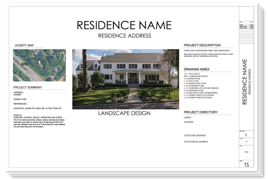
The title sheet serves as the introduction to the project and establishes the organization for the entire drawing set.

Although it typically contains very little construction information, it provides important project data that contractors, consultants, and permitting departments reference throughout the life of the project.

A typical title sheet includes:
  • Project name
  • Property address
  • Client information
  • Drawing index
  • Vicinity map
  • Consultant information
  • Revision history
  • General project information
  • Professional seal, if required


Many residential firms also include a perspective rendering or aerial visualization on the cover sheet to immediately communicate the design vision before readers begin reviewing the technical drawings.

2. General Notes

The general notes sheet establishes the standards and assumptions used throughout the drawing set.

Instead of repeating the same information across multiple sheets, designers centralize construction requirements in one location where contractors can reference them throughout the project.

General notes commonly address topics such as:
  • Contractor responsibilities
  • Utility verification
  • Existing tree protection
  • Construction tolerances
  • Material installation requirements
  • Planting standards
  • Site verification
  • Survey limitations
  • Coordination with other trades


Although these notes may seem routine, they help define expectations before construction begins and reduce misunderstandings later in the project.

3. Existing Conditions Plan

Before proposing new work, it's important to document the site as it currently exists.

The existing conditions plan becomes the foundation for every drawing that follows. It records the physical characteristics of the property and provides a common reference point for design decisions.

Typical information includes:
  • Property boundaries
  • Easements
  • Existing residence
  • Driveways
  • Sidewalks
  • Pools
  • Existing trees
  • Utilities
  • Drainage structures
  • Survey information
  • Spot elevations when applicable


Accurate existing conditions help designers coordinate new work with existing site features while minimizing conflicts during construction.

4. Demolition Plan

Not every feature on a property is intended to remain.

The demolition plan identifies what will be removed before new construction begins, allowing contractors to separate demolition work from proposed improvements.

Items commonly shown include:
  • Existing patios
  • Concrete walkways
  • Retaining walls
  • Fencing
  • Trees designated for removal
  • Shrubs scheduled for removal
  • Existing landscape beds
  • Pools or site structures
  • Irrigation components to abandon


Using dedicated demolition graphics—such as dashed lines, hatch patterns, or demolition symbols—helps distinguish existing work from proposed construction and keeps the remaining drawings much easier to read.

5. Overall Site Plan

The overall site plan is often the drawing clients reference most because it communicates the complete design in a single view.

Rather than focusing on one specific discipline, this sheet brings together the major design elements so readers can understand how the entire property functions as one cohesive landscape.

A typical site plan includes:
  • Patios
  • Walkways
  • Driveways
  • Pools
  • Outdoor kitchens
  • Fire features
  • Planting areas
  • Lawn areas
  • Walls
  • Steps
  • Site furnishings
  • Major dimensions


Because it combines all primary design elements, this drawing often becomes the central reference sheet throughout the project.

6. Hardscape Plan

While the overall site plan presents the complete design, the hardscape plan isolates the constructed portions of the landscape.

This allows contractors responsible for masonry, concrete, decking, and site construction to focus on the information relevant to their work without unnecessary visual distraction.

A hardscape plan typically includes:
  • Paver layouts
  • Natural stone paving
  • Concrete surfaces
  • Gravel areas
  • Retaining walls
  • Seat walls
  • Steps
  • Coping
  • Outdoor kitchens
  • Fire pits
  • Material callouts
  • Joint patterns
  • Critical dimensions


Separating hardscape information onto its own sheet improves readability and provides contractors with the information needed to accurately estimate and construct the project.

7. Planting Plan

The planting plan documents every living element within the proposed landscape.

Rather than illustrating only where plants are located, the drawing also communicates the quantity, species, and installation information necessary for procurement and installation.

A planting plan commonly includes:
  • Tree locations
  • Shrub locations
  • Perennials
  • Ornamental grasses
  • Groundcovers
  • Plant symbols
  • Botanical names
  • Common names
  • Quantities
  • Container sizes
  • Planting schedule


Many designers develop graphic symbols that remain consistent across projects, allowing contractors to quickly identify planting types while reducing confusion during installation.

8. Lighting Plan

Landscape lighting is often coordinated after planting and hardscape have been established, but it deserves its own dedicated drawing.

A lighting plan communicates fixture locations, wiring paths, and system organization so lighting contractors can install the system efficiently while coordinating with other trades.

A typical lighting plan includes:
  • Path lights
  • Uplights
  • Downlights
  • Well lights
  • Step lights
  • Wall-mounted fixtures
  • Transformers
  • Fixture schedule


Planning lighting as its own drawing also helps identify potential conflicts with trees, irrigation, utilities, and paving before construction begins.

9. Construction Details

Plan drawings explain where things belong.
Construction details explain how they should be built.

These enlarged drawings provide information that cannot be communicated effectively at the scale of a site plan. They illustrate assembly methods, dimensions, material layers, and installation techniques that contractors rely on throughout construction.

Construction details commonly include:
  • Tree planting details
  • Shrub planting details
  • Paver edge restraints
  • Retaining wall sections
  • Stair construction
  • Footing details
  • Pergola foundations
  • Fence connections


Without these drawings, contractors are often forced to make assumptions that may differ from the designer's original intent.

10. Elevations and Sections

Plan views communicate horizontal relationships, but they cannot fully describe changes in height, depth, or vertical construction.

Elevations and sections provide that missing information by illustrating how landscape elements appear from the side or through a cut section.

These drawings are commonly used for:
  • Retaining walls
  • Outdoor kitchens
  • Fireplaces
  • Pergolas
  • Pools
  • Grade transitions
  • Seat walls
  • Stair relationships


Sections are particularly valuable when coordinating with architects and builders because they clarify how outdoor spaces connect to the house and surrounding grades.

11. Photorealistic Renderings

Although renderings are not construction documents, they have become an important part of the modern residential design process.

Technical drawings communicate dimensions and specifications, while renderings communicate atmosphere, materials, scale, and experience.

Clients often find it much easier to evaluate design decisions after seeing a realistic visualization of the proposed landscape.

Renderings can help communicate:
  • Material selections
  • Planting maturity
  • Outdoor lighting effects
  • Spatial relationships
  • Views from the home
  • Outdoor living experiences
  • Overall design character


By helping clients understand the project before construction begins, renderings often reduce revisions later in the design process and improve confidence during approvals.

Typical Sheet Order for a Landscape Architecture Plan

While every office develops its own standards, a professional residential landscape architecture drawing set commonly follows this sequence:
  1. Title Sheet: Project information and drawing index
  2. General Notes: Construction standards and project notes
  3. Existing Conditions Plan: Existing site documentation
  4. Demolition Plan: Existing items scheduled for removal
  5. Overall Site Plan: Complete proposed landscape layout
  6. Hardscape Plan: Constructed landscape elements and materials
  7. Planting Plan: Trees, shrubs, planting schedule, and plant locations
  8. Lighting Plan: Fixture layout and lighting system organization
  9. Construction Details: Assembly methods and installation drawings
  10. Elevations & Sections: Vertical relationships and construction clarification
  11. Photorealistic Renderings: Client visualization and design communication
This sequence creates a logical progression through the project, beginning with site documentation, moving into proposed design, and finishing with the technical information needed to construct the landscape accurately.

Learn How to Use AutoCAD to Design Full Landscapes

Software Used to Produce a Landscape Architecture Plan

Professional landscape architecture plans are rarely created using a single software program. Instead, designers use several specialized applications, each serving a different role within the workflow.

A common residential workflow includes:
  • AutoCAD for drafting construction documents and organizing drawing sheets
  • Rhino 3D or SketchUp for developing three-dimensional models
  • Enscape or Lumion for creating photorealistic renderings
  • Adobe InDesign for assembling presentation packages and client deliverables
  • Adobe Photoshop for image editing, diagrams, and presentation graphics


Using multiple programs allows designers to move efficiently from technical drafting to visualization while maintaining consistency throughout the project.

Learn How to Use AutoCAD to Design Full Landscapes